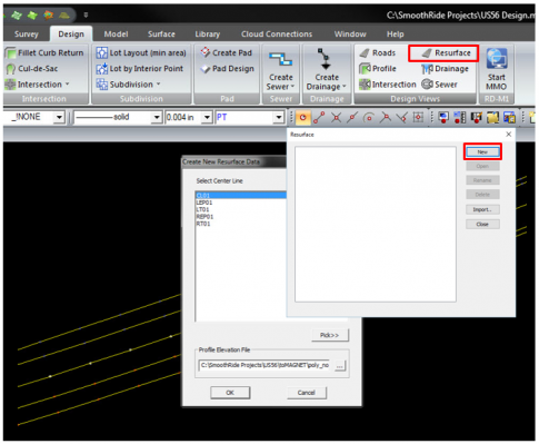
Create New Resurface Data
- Open Design ribbon
- In Design View group, Select Resurface button
- Select New button
- Select all road lines
- Press Esc on keyboard
- Select string to use as Center Line
- Select OK
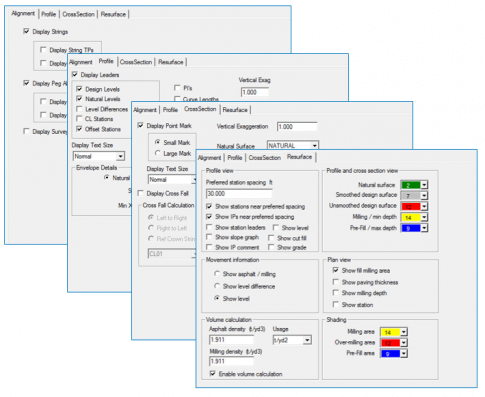
Customize Resurface View
- In Settings ribbon
- All buttons open Road Display Settings
- Buttons are the tabs
-
Changes what is displayed in various views
- Alignment – plan view
- Profile – profile view
- CrossSection – cross-section view
- Resurface – multiple views
Alignment Tab
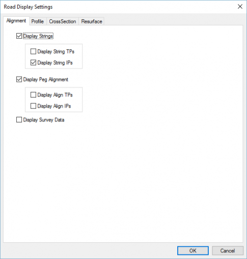
- Select the Alignment tab
- Check Display Strings and Display Peg Alignment
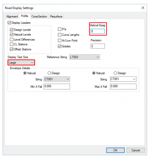
Profile Tab
- Select the Profile tab
- Set Display Text Size to Large
- Enter 5.000 for Vertical Exag
CrossSection Tab
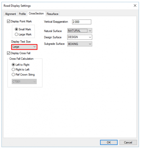
- Select the CrossSection tab
- Set Display Text Size to large
- Check box for Display Cross Fall
- Enter 2.000 for Vertical Exaggeration
Resurface Tab
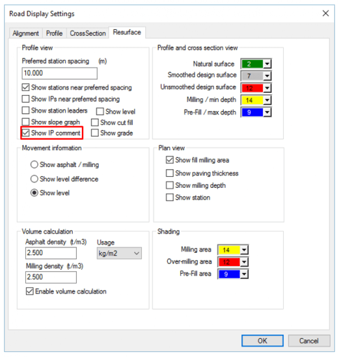
- Uncheck Show IPs near preferred spacing
- Check Show IP comment
- Enter Asphalt density
- Enter Milling density
- Select OK
Customize Resurface View
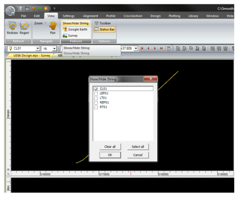
- Open View ribbon
- Select Show/Hide String
- Select Clear all to uncheck all strings
- Check the box for the string to use as the profile reference (typically the centerline)
- Select OK to close
- Select in the profile view
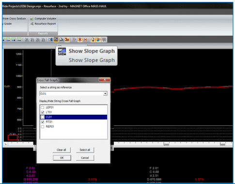
- Select Show Slope Graph button in Resurface toolbar
- Double-click the cross fall graph label
- Select reference string
- Check strings to display in graph
- Select OK to close
-
Slope Graph displays relationship of strings selected to the reference string in percent of grade for quick identification of areas with crown, super elevation, and transition.
