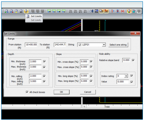
Define Limits
- Select in the profile view
- Select Set Limits button in the Resurfacing toolbar
- Enter design limitations for thickness and slope
- Select OK
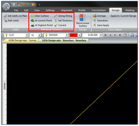
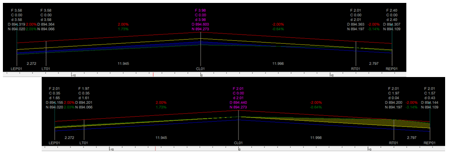
Apply Thickness
- In Design ribbon
-
Minimum Thickness group
- Over Surface
- At Lowest Point
- At Highest Point
- Along String
- Set Thickness
- Correct
-
Over Surface
- Apply minimum thickness over natural surface
- Use for no mill situation
-
Along String
- Apply minimum thickness over selected string(s)
- Same as Over Surface at defaults
-
At Lowest Point
- Preserves cross slope
- Minimum thickness at lowest point in cross-section
- For no mill project
-
At Highest Point
- Preserves cross slope
- Minimum thickness at highest point in cross-section
- For forced mill project
-
Set Thickness
- Enter thickness to add to natural surface
- Creates mill to minimum fill thickness
- For forced mill project
-
Correct
- Changes limit of minimum fill thickness to insure minimum mill
- Does not change design surface
- For forced mill project
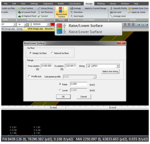
Lift to Yield
- Open Design ribbon
- Select Raise/Lower Surface button
-
Enter amount to raise or lower to match desired yield volume
- Raise to decrease mill and increase fill
- Lower to decrease fill and increase mill
- Minimum on fill not on mill
- No maximums
- Select OK
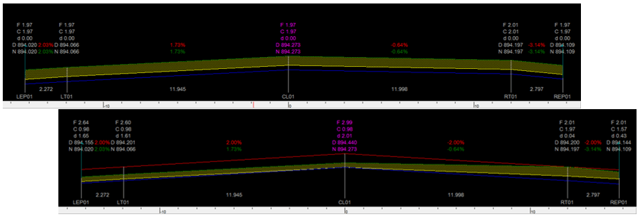
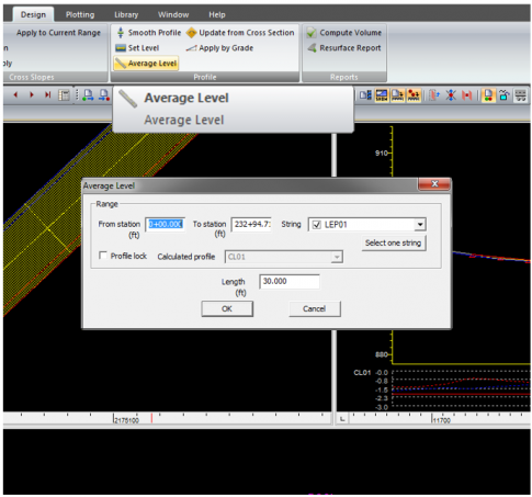
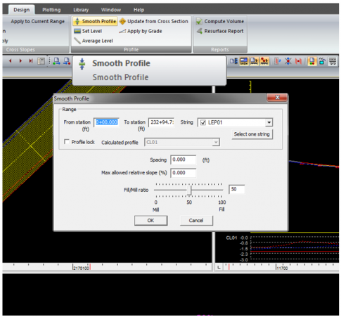
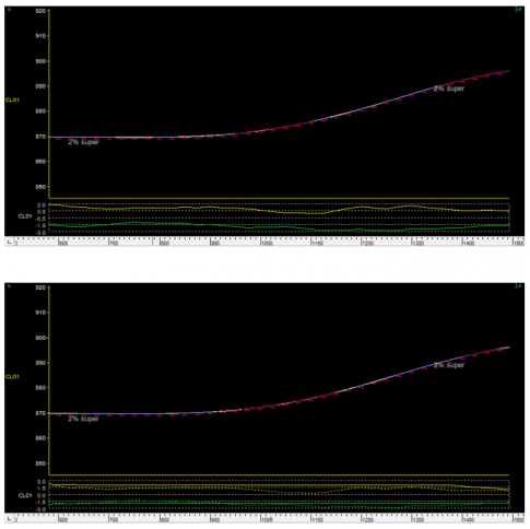
Smooth Profile
- Open Design ribbon
- Select Average Level button
- Enter range and select strings to average
-
Enter Length for the average
- Half ahead and half behind
-
Select OK
- Cumulative effect when applied multiple times
- Running elevation average – same effect as a mechanical ski
- Open Design ribbon
- Select Smooth Profile button
- Enter range and select strings to affect
- Enter spacing and relative slope
-
Select or enter fill/mill ratio
- 0 = only mill
- 100 = only fill
-
Select OK
- Forces profile into parameters
- Not always a solution
- No change if applied multiple times
- Best used to take out dips or bumps not resolved by Average Level
Manually Address Problem Areas
- Select in profile view
- Icons become active in Resurface toolbar
- Set start and end stations in profile view
- Select drag mode
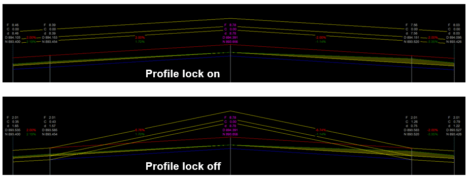
- Set profile lock
- Drag intersection point to desired location

Drag Mode
-
Lift
- Maintains shape within limits
-
Bend
- Bends shape from drag point to limits
-
Straight
- Straight grade from drag point to limits
-
Off
- Straight grade from drag point to nearest IPs
Profile Lock
- Locks all profiles together
- Dragging one profile affects all profiles
- Maintains cross slopes
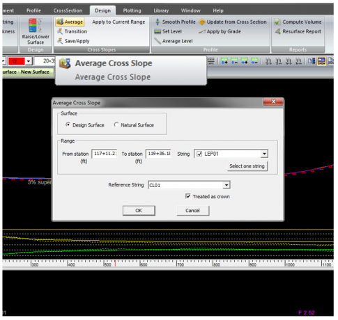
Define Cross Slopes
- Average
- Apply to Current Range
- Transition
Average
- Set start and end stations in profile view
- Open Design ribbon
- Select Average button
- Select surface from which average cross slopes
-
Select crown mode
- Checked for crowned
- Uncheck for super elevation
- Select OK
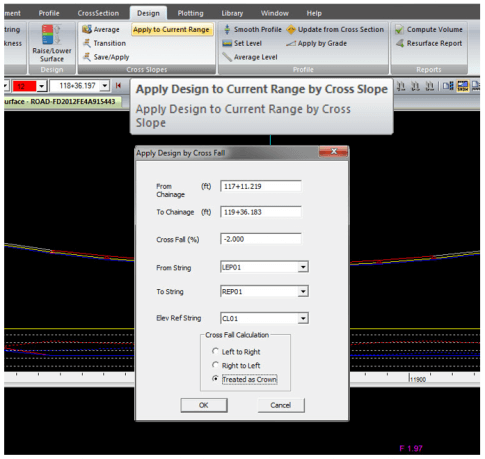
Apply to Current Range
- Open Design ribbon
- Select Apply to Current Range button
- Enter station range
- Enter desired cross fall
- Select string range
- Select how to apply cross fall
- Select OK
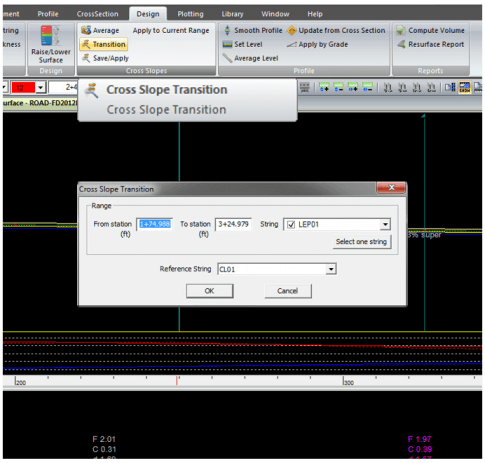
Transition
- Open Design ribbon
- Select Transition button
- Enter station range
- Select strings
- Select OK