- After all AT processing (and GCP matching if necessary) for a given photo block has been done, the next step is to perform 3D Mesh Reconstruction.
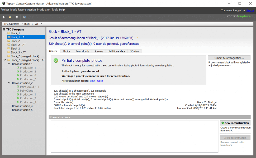
- Select the photo block to be processed from the left side of the screen and select the General tab.
- Select New reconstruction located at the bottom right of the main window.
-
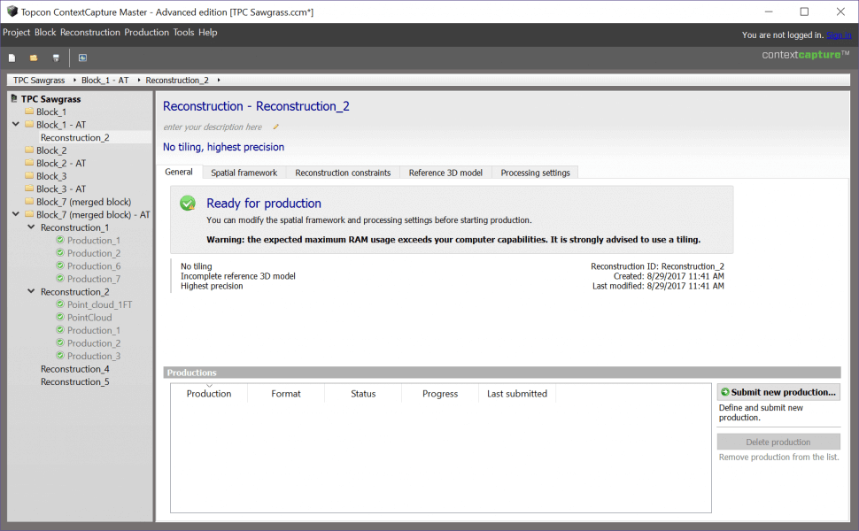
For the new reconstruction, a warning may appear on the general tab depending on the size of the project (i.e. number of gigapixels) and the processing PC’s current amount of system RAM:
- Warning: the expected RAM usage exceeds your computer capabilities. It is strongly advised to use a tiling.
-
If this warning occurs, the data will need to be broken up into smaller tiles in order to process and create the 3D Mesh.
-
If a tiling isn’t used despite the warning message, the 3D Mesh reconstruction will fail as it will exceed the max amount of system RAM the PC has available.
-
- To setup the tiling for a given dataset, Select the Spatial Framework tab.
-
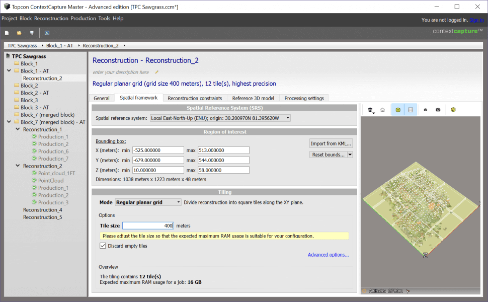
On the Spatial Framework screen, configure the following:
- Select the Spatial Reference system to be used when creating the 3D Mesh.
-
To process just a portion of the dataset if desired, configure the following:
- Select Import from KML to bring in a .kml file from Google Earth to create a custom region of interest.
- Edit the current region of interest using the edit region of interest button.
-
The tiling mode of the dataset can be configured to the following:
-
No Tiling – 3D Mesh will be created as 1x tile.
-
Planar Grid Tiling – divides the 3D Mesh into square tiles along the XY plane. For datasets with small/moderate changes in elevation throughout.
-
Volumetric Tiling – divides the 3D Mesh into cubic tiles. For datasets with large spikes in elevation (i.e. buildings, skyscrapers, etc.)
-
Adaptive tiling – tiling is determined by user defined target system RAM usage.
-
-
If using a planar or volumetric tiling, using a tile size that is too small or too large can result in longer processing times as this effects RAM usage.
-
Similarly, for adaptive tiling, using too much or too little system RAM can result in longer processing times.
-
Generally, at the maximum, choose a tile size or target RAM usage that does not exceed 80% of the system RAM available.
-
However, for faster processing times of the 3D Mesh, 50% RAM usage works well, but will create more tiles.
-
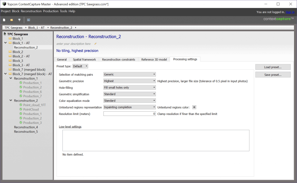
- Select the Processing Settings tab.
-
On the Processing Settings tab, leave all settings at their defaults, except for the following:
- Geometric Precision – depending on the setting, this will effect quality of 3D mesh reconstruction and processing time.
-
Geometric Precision can be set to the following:
- Ultra: high RAM usage and computational time – not recommended. Ultra mode is 4x slower, and takes 4x more memory than High or Highest mode.
- Highest (default): larger file size (tolerance of 0.5 pixel in input photos). High and Highest modes are similar in terms of computation time and memory consumption.
-
High: smaller file size (tolerance of 1 pixel in input photos). High and Highest modes are similar in terms of computation time and memory consumption.
-
Medium: best suited for Orthophoto/DSM productions (tolerance of 2 pixels in input photos). The fastest and most memory-efficient mode. Medium mode is 2-3 times faster, and takes 4 times less memory than High or Highest mode.
- Select the General tab.
- Select Submit new production from the bottom right of the screen.
- Enter a name for the production and select Next.
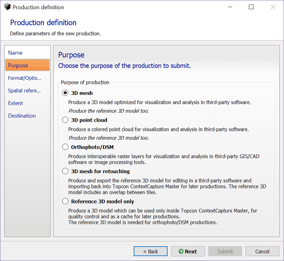
- For the purpose of production, select the 3D Mesh radio button.
- Once finished, select Next.
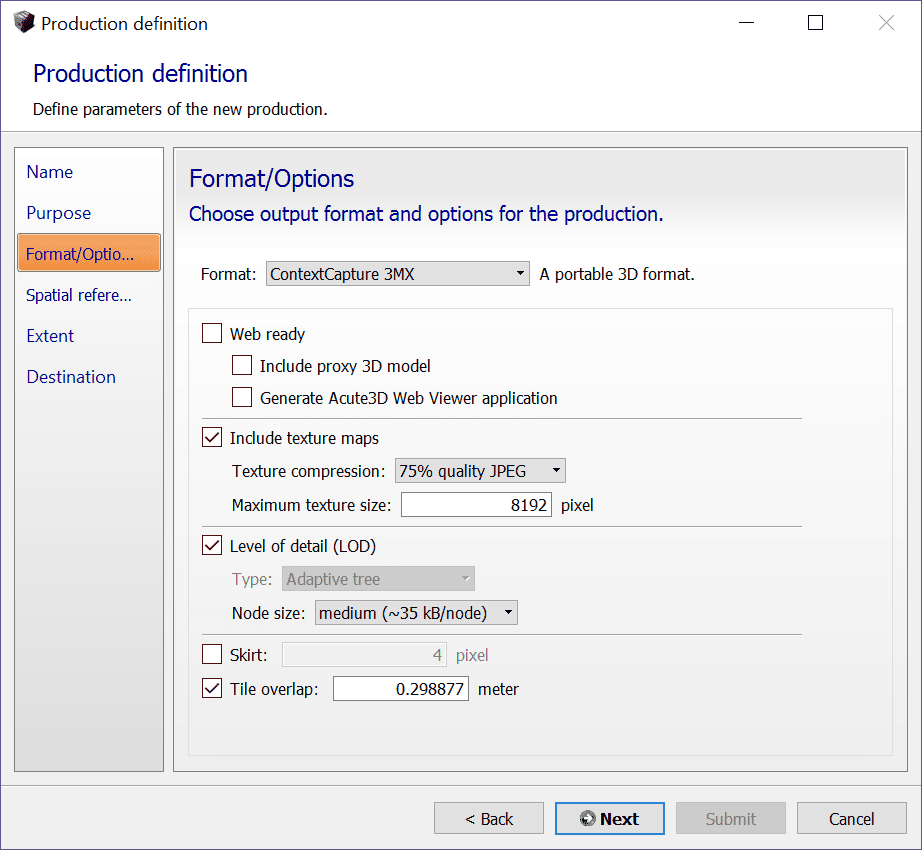
- On the Format/Options screen, choose the format the 3D Mesh will be created in as necessary. The available configuration settings will change depending on the format chosen.
- By default, the format will be set to Context Capture 3MX (for working with Topcon Context Capture Editor).
- All settings for the 3MX format can be left at their default settings.
- Once finished, select Next.
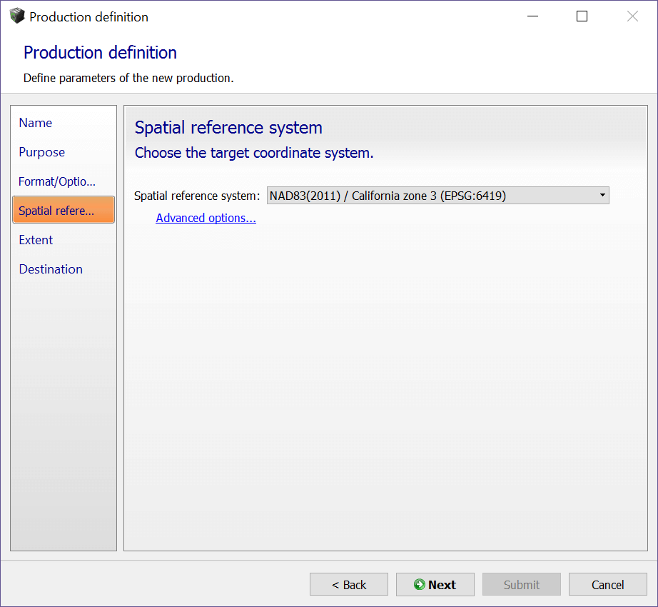
- On the Spatial reference system screen, select the spatial reference system for the 3D Mesh reconstruction from the pull down menu.
- Once finished, select Next.
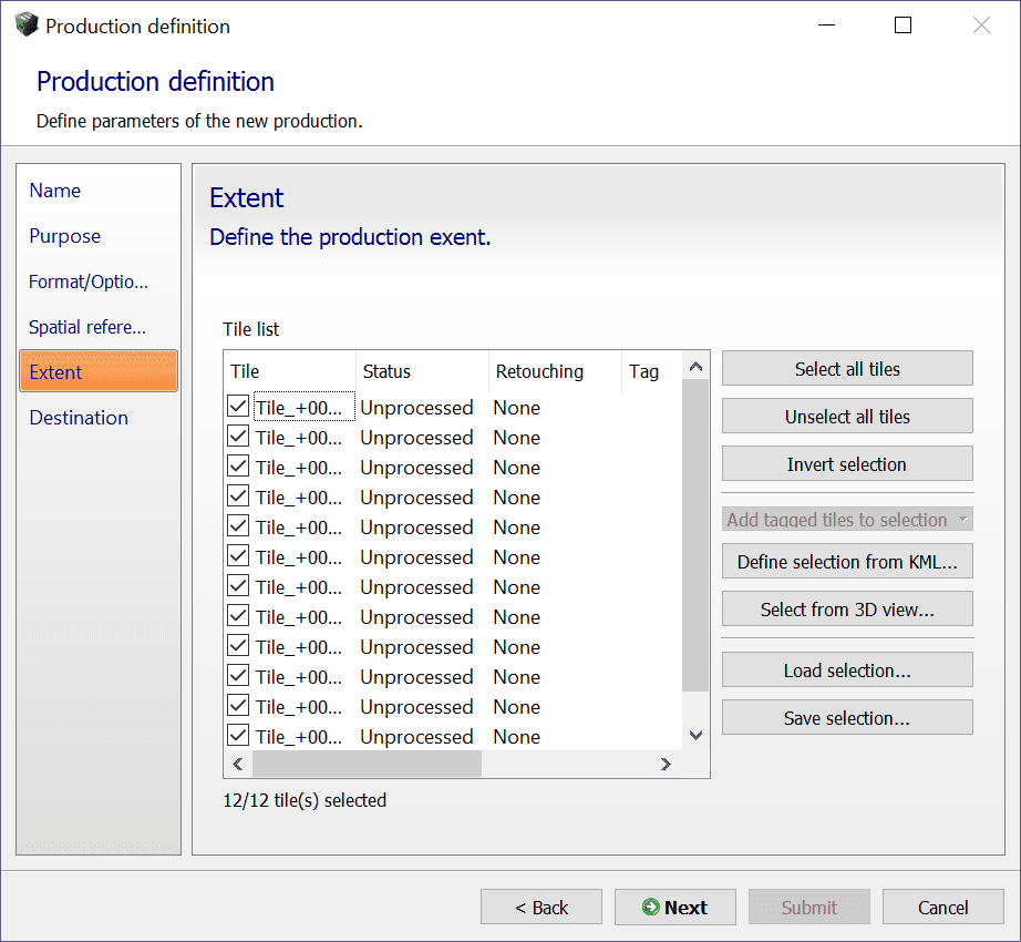
- On the Extent screen, select the tiles that will be used for 3D Mesh reconstruction. All tiles will be generated by default.
- However, if necessary, the user can generate only the specific tiles needed rather than all tiles for a particular dataset to speed up processing time.
- To select or deselect which tiles will be generated during 3D Mesh reconstruction, select the Select from 3D View button and choose on the 3D View which tiles to generate.
- Once finished, select Next.
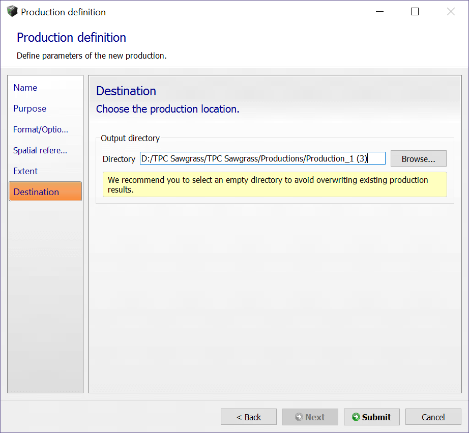
- On the Destination screen, select Browse and navigate to the directory on the PC to save the 3D Mesh.
- Once finished, select Submit to begin 3D Mesh reconstruction.
- Please note 3D Mesh reconstruction is the most time consuming processing step for UAS data (depending on the size of the project, processing PC specs and processing settings configured).
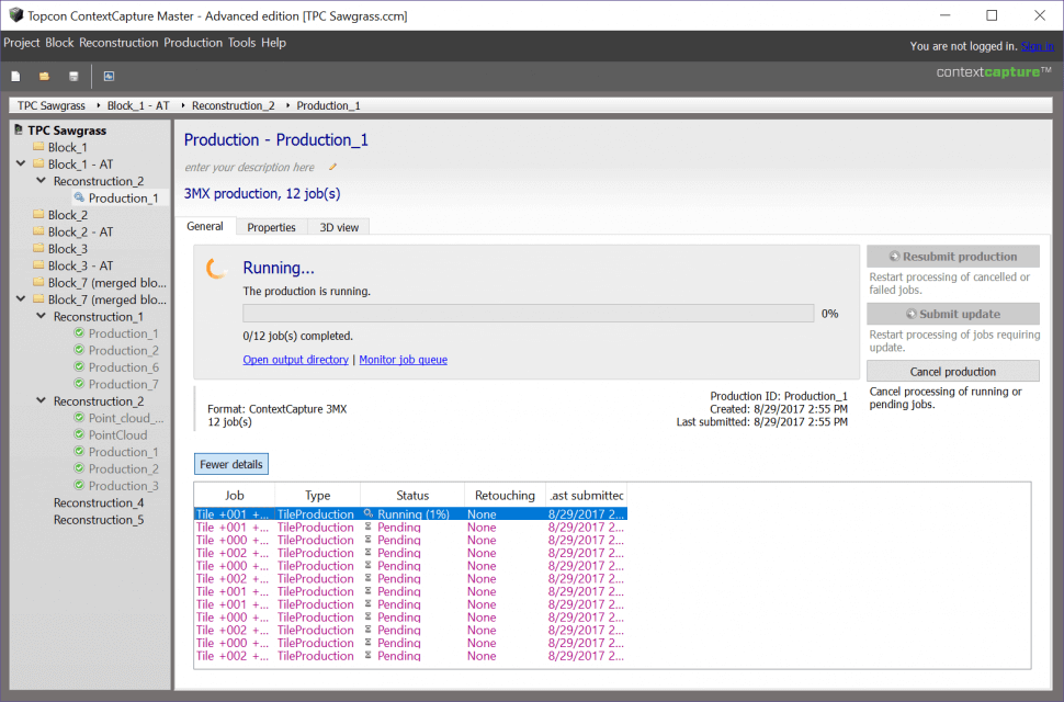
- After submitting the production, the user can view the processing percentage for each tile in the 3D Mesh reconstruction as well as the overall progress of the production.
- To view this, select the production being generated from the left side of the screen and select More Details to see this information.
- Also, as individual tiles are completed, the user can view the completed tiles by selecting the 3D View tab for the production (or select Open with Acute 3D Viewer).