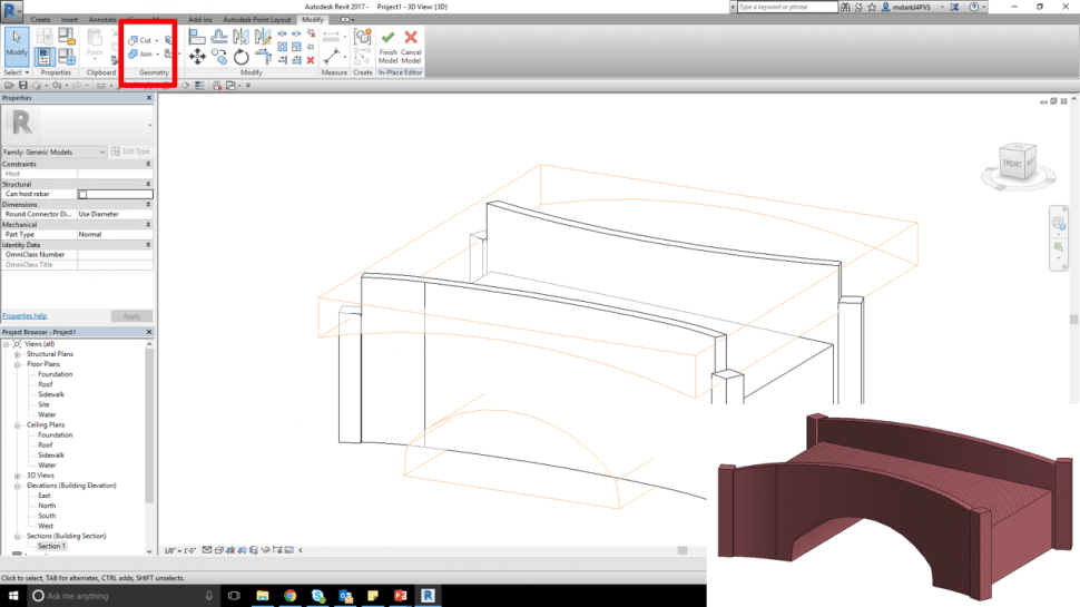
- Work your way through by adding solid extrusions and subtracting void bodies
- You can use the Cut and Join features in the Geometry group to do boolean operations
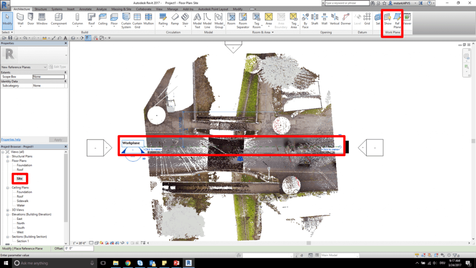
- Double click and open Section 1 in Project Browser
- Go to Architecture tab / Build / Component / Model In-place
- Choose Generic Model as Family Category
- Assign a Name to it
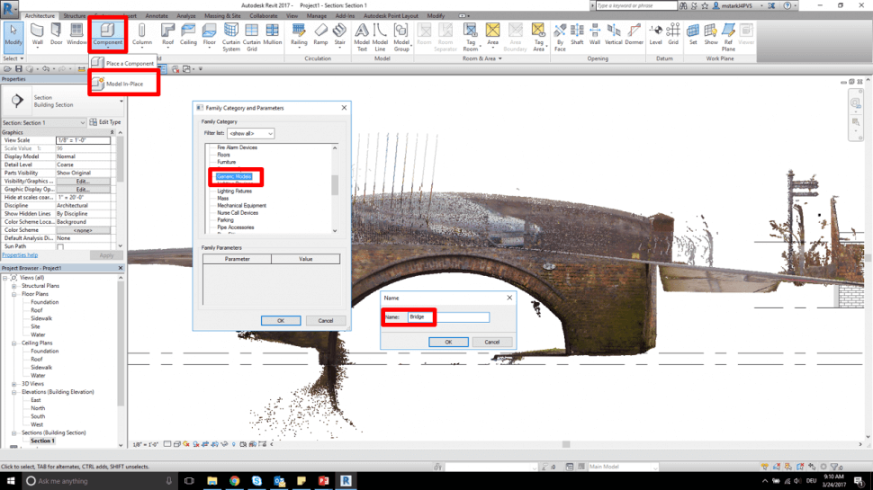
- Select Extrusion from the Forms group
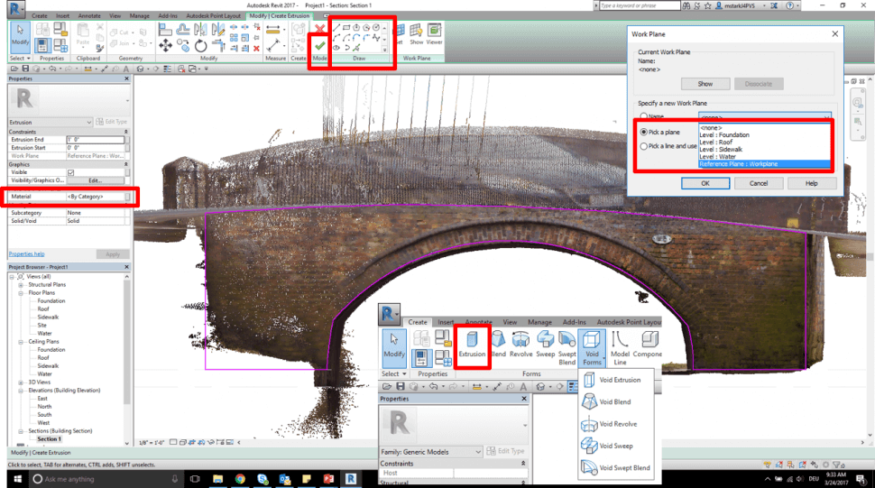
- Select formerly created Reference Plane as Work Plane
- Use the Draw options to trace and draw the shape of the bridge
- Assign a Material if you want to
- Make sure that the Sketch is closed
- Hit the green checkmark to finish the sketch
- Double-click on Floor Plan Site in Project Browser
- Select the extrusion
- Drag the grips of the extrusion to cover at least the whole extents of the bridge
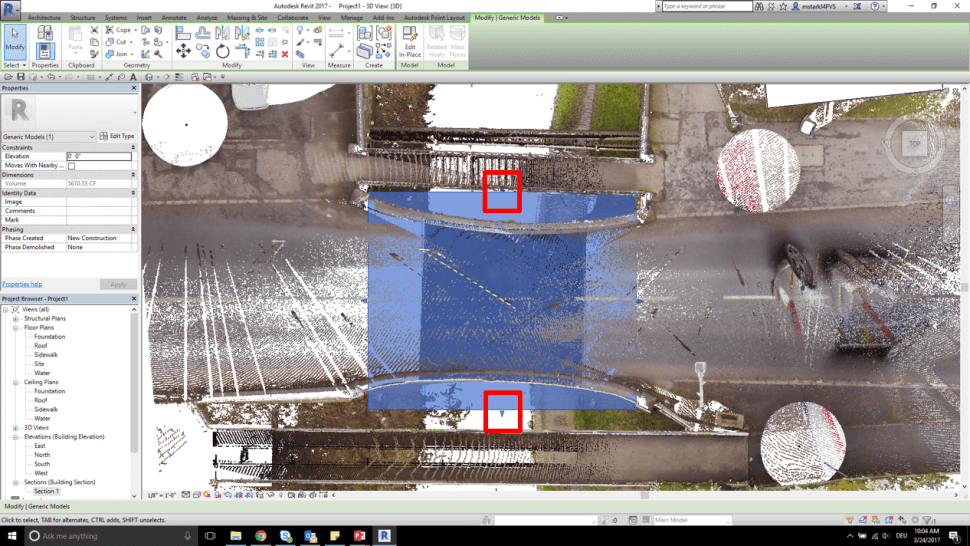
- Select the extrusion and select Edit In-place
- Select Void Extrusion as a form
- Trace and draw void forms by using the Draw tools
- Make sure that the sketches are closed
- Hit the green checkmark to finish the Sketch
- Hit the green checkmark to finish the Model
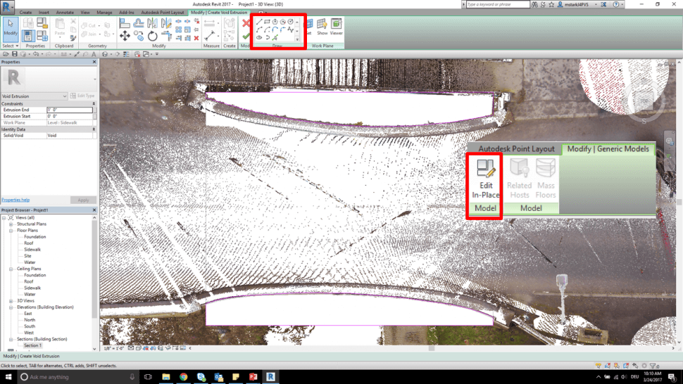
- Go to the 3D view
- Select void extrusion and use the vertical grips to extend the void vertically in order to fully cut the solid extrusion
- Hit vv on your keyboard and uncheck the point cloud in the visibility settings
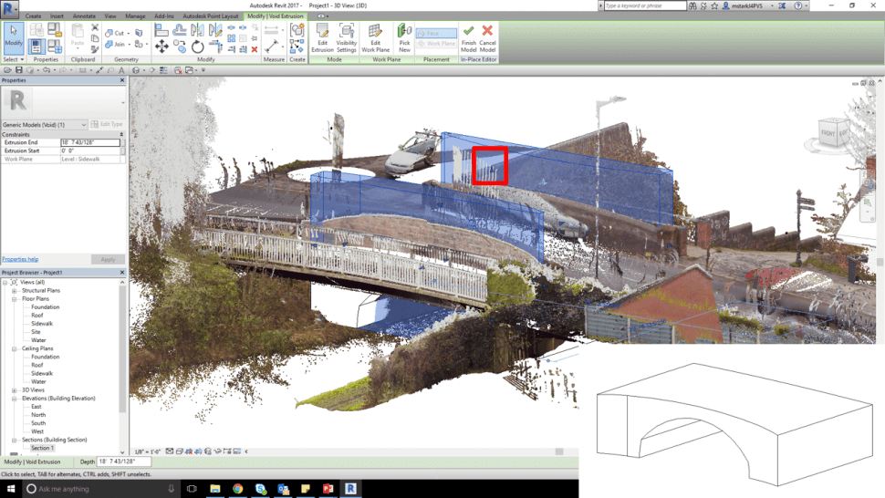
- Work your way through by adding solid extrusions and subtracting void bodies
- You can use the Cut and Join features in the Geometry group to do boolean operations
