Creating a MAVinci Desktop Session
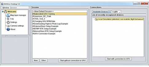
- Open MAVinci Desktop on the PC. On the Welcome screen under the Sessions list, select New.
- Select the New Folder button and enter a name for the session. Once finished, select Ok.
- Select Ok again to return to the Sessions list on the Welcome screen.
- Select the newly created session from the Sessions list and select Start without connection to UAV. The Map View will appear.
Creating a Polygon Flight Plan
-
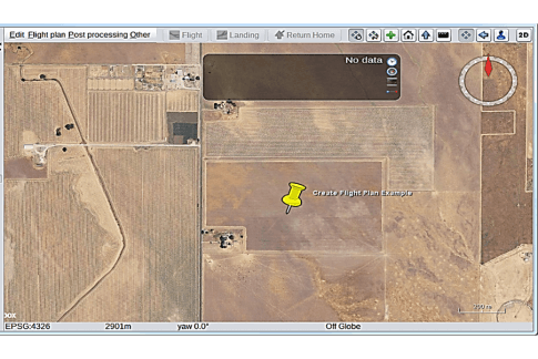
On the Map View, zoom into the AOI to be collected with the UAS.
- Note an internet connection is required to cache the background maps on the Map View.
- An efficient way to zoom into the AOI is to load a previously created Google Earth KML/KMZ file of the project area which will contain its location.
-
To load a KML/KMZ file in MAVinci Desktop:
- On the Map View, select Other – Load KML/SHP from File.
- Navigate to the location of the KML/KMZ file on the user’s PC.
- Select Open.
- The Map View will then zoom into the area located in the KML/KMZ file automatically.
Creating a Polygon Flight Plan
- Select Flight Plan – New Flight Plan – Polygon.
- On the Map View, left click to create the corners of the AOI to be collected with the UAS.
-
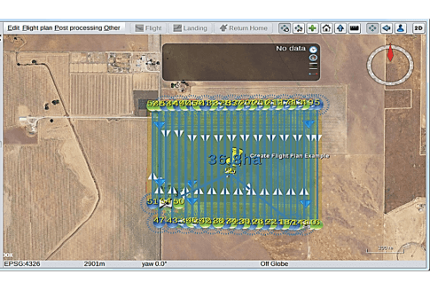
Once finished, select Edit – Recalculate Flight Plan to create the flight plan.
- The area to be covered by the AOI created is displayed on the Map View in hectares or acres.
- Please note that the flight plan calculation will default to a yaw (heading) value of 0 degrees (North).
- Adjust the location of the home position (safety circle) as necessary.
Creating a Polygon Flight Plan
-
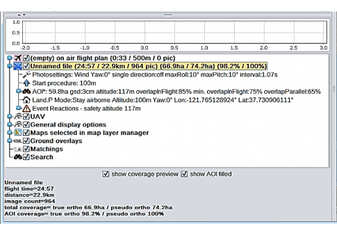
The metrics for the flight plan will be displayed on the Detail Panel on the lower left side of the screen, including:
- Estimated flight time (in minutes) - with no wind.
- Estimated number of images to be captured
- Estimated total area to be covered by the flight plan.
- Estimated total distance to be covered.
- On the Detail Panel, the calculated flight plan will be named Unnamed file. To save the flight plan to the user’s PC:
- Highlight the flight plan in the Detail Panel.
- Select Flight Plan – Save flight plan As.
- Enter a name for the flight plan and select Save.
Adjusting GSD/Altitude Settings
- The resolution (pixel size) of the collected images for a particular flight plan can be adjusted by changing the GSD.
- Modifying the GSD also adjusts the UAV flight altitude automatically.
-
To adjust the GSD of the collected images and the flight altitude:
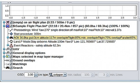
- On the Detail Panel, for a calculated flight plan, select AOI.
- Adjust the GSD setting accordingly (default is 3cm). Press Enter. The flight altitude under AOI will update in accordance with the set GSD.
- Confirm that the flight altitude calculated by MAVinci Desktop does not exceed any altitude restrictions where the UAV will be flown. If so, adjust the GSD.
- The metrics of the flight plan will also adjust automatically corresponding to the set GSD.
Adjusting Flight Plan for Wind Direction
- To reduce the effects of crosswinds on the UAV during flight, most flight plans will need to compensate for wind direction prior to flight.
-
To adjust the flight plan for the wind direction:
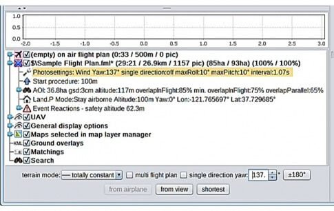
- On the Detail Panel, for a calculated flight plan, select Photosettings.
- Adjust the yaw angle accordingly (default is 0 degrees) until the flight lines in the flight plan correspond to the current wind direction.
- The orientation of the flight plan in the Map View and the metrics of the flight plan will adjust automatically according to the yaw angle entered.
Adjusting Flight Plan for Shortest Time
- If there are no winds present around the AOI prior to flight, then the yaw (heading) angle of the flight plan can be adjusted for shortest flight time.
-
To adjust the flight plan for shortest flight time:
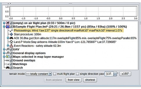
- On the Detail Panel, for a calculated flight plan, select Photosettings.
- Select Shortest.
- The orientation of the flight plan in the Map View and metrics of the flight plan will adjust automatically for the shortest flight time.
Adjusting Flight Plan for Single Direction
- To reduce the effects of strong tailwinds on the aircraft during flight, the flight plan can be adjusted to capture images in a single direction only.
- To adjust the flight plan for single direction capture:
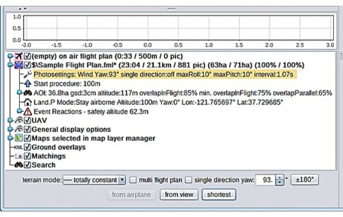
- On the Detail Panel, for a calculated flight plan, select Photosettings.
- Check the single direction checkbox.
- All flight lines will be doubled to ensure adequate image overlap. Flight time will noticeably increase.
- The metrics of the flight plan will adjust automatically for single direction capture.
Creating a Terrain Flight Plan
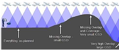
- Flying at a constant flight altitude is not always recommended – depends on the terrain of the AOI.
- In these types of environments where the elevation AGL in the area varies greatly, the set GSD will vary if you fly at a consistent flight altitude.
-
Also, in these types of areas with large elevation differences AGL:
- The image overlap may be insufficient in some parts of the dataset for proper data processing.
- There is an increased risk of collision with mountains, trees, or other features when flying at a constant flight altitude.
- MAVinci Desktop allows the user to calculate a flight plan to follow the terrain to preserve the set GSD when the UAV will be flying in areas that contain large elevation differences AGL.
- When calculating a given flight plan, the software will automatically determine whether a terrain flight plan can be utilized.
Creating a Terrain Flight Plan
- Select Flight Plan – New Flight Plan – Polygon.
- On the Map View, left click to create the corners of the AOI to be collected with the UAS.
- Once finished, select Edit – Recalculate Flight Plan.
- If a warning message appears similar to the image when calculating the flight plan, then a terrain flight plan can be used.
- Select Yes.

Creating a Terrain Flight Plan
-
To adjust the flight plan to follow the terrain:
- On the Detail Panel, for a calculated flight plan, select Photosettings.
- Select for Terrain.
- The orientation of the flight plan in the Map View and metrics of the flight plan will adjust automatically to account for the terrain of the AOI.
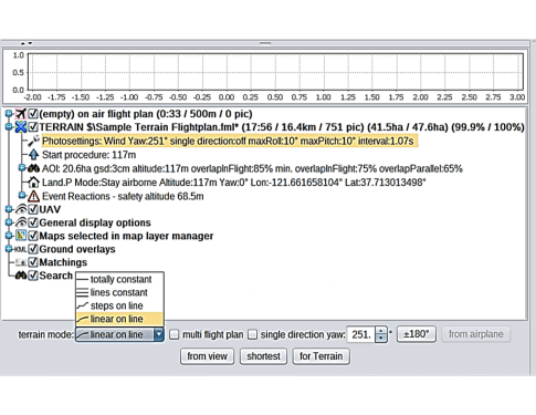
Terrain Mode Flight Plan Settings
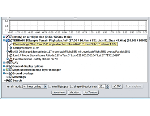
- When creating a terrain flight plan, the user has a few options that can be configured on how the flight lines will follow the terrain.
- These options are configured via the terrain mode pull down menu under the Photosettings for a given calculated flight plan.
-
Terrain Mode – Totally Constant:
- Flight lines are not adapted for the terrain. All flight lines will be flown at a constant flight altitude.
- Not recommended to use if MAVinci Desktop determines that a terrain flight plan can be utilized when calculating a flight plan.
-
Terrain Mode – Lines Constant:
- Each flight line will have its own flight altitude.
- The flight altitude for each flight line is constant.
- Important to check the variation in terrain for each flight line (large discrepancies can create an inconsistent GSD). MAVinci will check this and warn the user when transmitting the flight plan.
-
Terrain Mode – Steps on Line:
- Additional waypoints are added along the flight line such that the flight altitude is adapted to the terrain more finely.
- Target flight altitude is changed from one waypoint to the next. The UAV flies horizontally until the next ascent or descent at the next waypoint
-
Terrain Mode – Linear on Line:
- Not available to user’s running v4.x firmware.
- Default terrain mode when using v5.x firmware.
- Additional waypoints are added along the flight line such that the flight altitude is adapted to the terrain more finely.
- The UAV evenly ascends or descends between waypoints in the flight line yielding a smooth adaptation of the flight lines to the terrain.
