Laser setup tips
The two main elements to setting the laser up correctly are:
- Laser placement
- Laser axis alignment
If the laser is incorrectly placed, is uncalibrated, or is misaligned, the cost in time and money to fix any one of these problems can cause delays in completing a project.
When choosing a location to place the laser transmitter, remember the following two recommendations.
1. Minimize the working distance from the laser.
As the distance from the laser transmitter increases, grade accuracy decreases. The following factors affect grade at long distances:
- Accuracy of individual laser instruments
- Ground vibration from machinery working near the laser transmitter
- Calibration error
- Curvature of the earth
- Laser movement from blowing wind
- Atmospheric conditions
2. Keep the laser transmitter as low as possible.
Keeping the laser transmitter low where you can reach it will make setup and grade changing much easier. The transmitter and laser receiver on the machine will also be more stable. On windy days, you may need to anchor the tripod to keep the laser from moving. The laser transmitter does not need to be above the machinery on the job. The benefits of keeping it low far outweigh the momentary loss of the laser beam due to passing equipment.
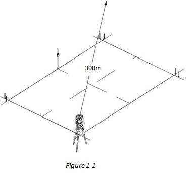
Small Project Laser Placement
On small projects, the laser transmitter can be placed off the working area (Figure 1-1). The working distance from your laser will indicate the type of project (small or large).
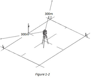
Large Project Laser Placement
On larger projects, place the laser in the center of the project to maximize the area you can grade, and minimize the distance from the laser (Figure 1-2). The working distance from your laser will indicate the type of project (large or small).
Laser Transmitter Axis Alignment
Manual Alignment
For lasers with manual alignment, follow these steps to correctly align the axis of your laser. This procedure should be followed, even for lasers that have a sighting scope (sighting scopes are never perfectly calibrated to the grade levelling mechanism of the laser).
- Locate or place two points parallel to the slope of the project. The hubs should be approximately 150-200m apart, or completely across the project on small jobs.
- Place the laser transmitter over one hub and dial in 0% slope on both axis.
- Align the laser by sight, pointing in toward the second hub.
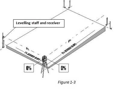
- Place the levelling staff and receiver on the second point and secure it to prevent movement.
The laser transmitter and grade rod should now be positioned so they are parallel to the direction of slope.
Set the laser sensor to centre the levelling bubble and get an on-grade signal, and lock it into position (Figure 1-3).
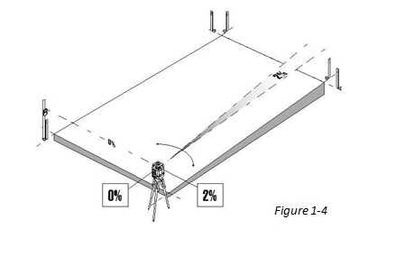
Dial the slope into the laser transmitter on the axis facing away from the detector. Leave the slope on the axis facing the detector at 0%. If the laser is aligned properly, the grade on the 0% axis will not change at the second hub, and the detector will still have and on-grade signal (Figure 1-4 ).
If you do not have an on-grade signal, rotate the laser until you get the on-grade signal.
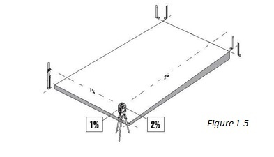
Once you have an on-grade signal, the laser is aligned. Dial in the desired slopes for your project (Figure 1-5).
Hardware setup
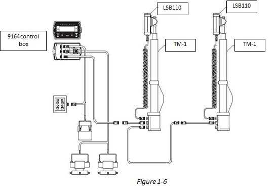
The System Five has several components that attach to each other using cables. The cables allow communication between the Sensor, the Control Box, and the Hydraulic Valves. When the Sensor detects a change in slope or elevation, it sends a signal to the Control Box, which then sends a pre-programmed, instructive signal to the Hydraulic Valves. Once the valves receive the signal, they raise or lower the blade according to the setup of the Control Box. Figure 1-6 shows generalized connection diagram for the dozer components.
After mounting the several System Five components to the implement, use the following procedure to get started System Five.
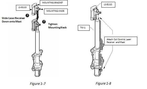
- Attach the Laser Receiver to the TM-1 mast (Figure 1-7)
- Connect the coil cord to the Laser Receiver and mast (Figure 1-8).
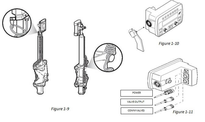
- Attach the cord to the snap hook, then pull it snug and wrap it around the shock mount (Figure1-9). This ensures that the force of the moving cord is not on the connectors.
- Attach the Control Box to a mounting bracket (Figure 1-10).
- Connect power, valve output and comm valves cables (Figure 1-11).
Setting system to a Benchmark
When setting the elevation reference, rotate the knob that corresponds to the left/front or right of the screen.
- Set the cutting edge, right and centre to correspond the masts, against a known benchmark.
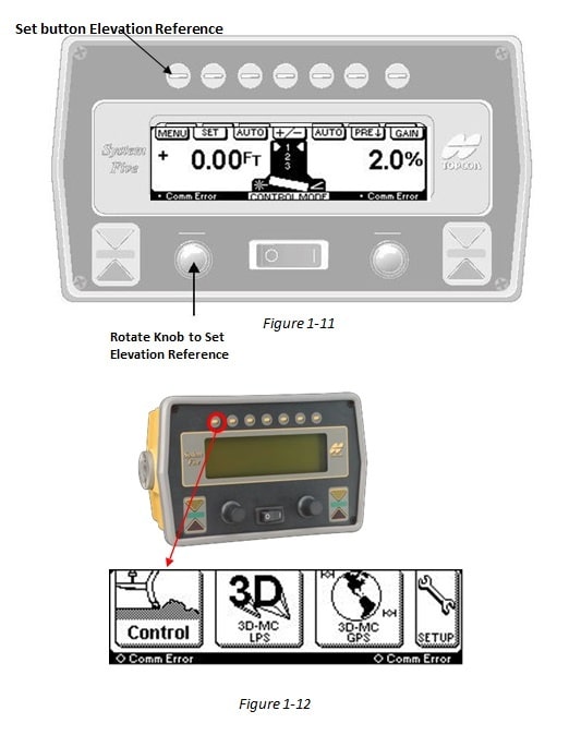
- On the main menu tap the button on the left for Control (Figure 1-12).
- Wind the masts up with the corresponding knob so that the receiver is set to the laser
- On the Levelling Mode screen, press the Set button.
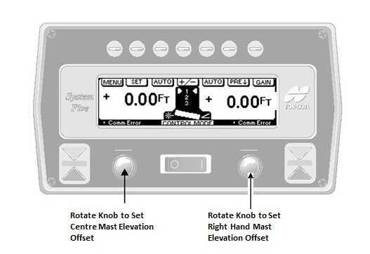
- On the Set screen, rotate the knob to select the elevation reference, or set reference to zero (Figure 1-11).
- Press the Enter button to save this number.
Adding an Elevation Offset
If your benchmark was set to the final graded level required then the system is set to work. If however your benchmark is set to a known offset from your desired finished level, you will need to apply this offset to the system.
- Rotate the knob to set the offset value to each receiver
- Now the system is set to an offset value you can either zero the number on the screen or continue working with known offset on screen
