Introduction
- The following information will cover the available options under the Control tab when using your Topcon 3D system. This information was created for software version 12.0.5.37 3D-MC and 12.0.7.15 3DMC Max.
- Control Points are typically supplied by the engineer and are contained within the Project file (.pt3). 3D-MC requires a least one localized control point. The process of localizing control points is performed using the Grade management system (Pocket 3D) and then copied into the 3D-MC system.
Control
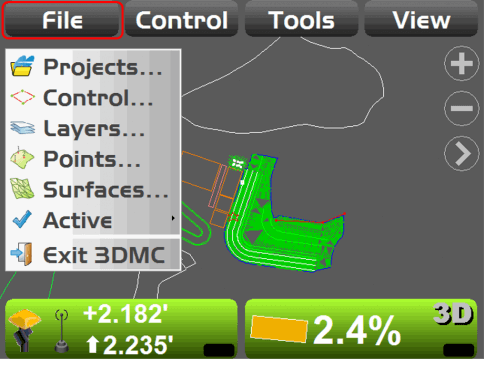
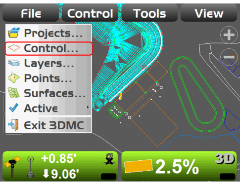
- To view the Control Points in the active Projects begin by touching the File tab then select the Control to see the available options.
Control Points
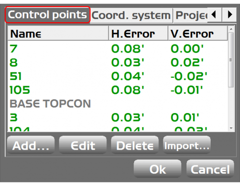
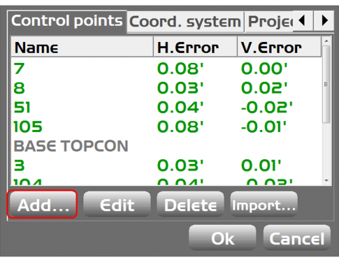
- In the Control Points screen all the Control points are displayed.
- Horizontal and Vertical errors are displayed for each of the control points that were used for the localization.
- If any of the localized horizontal or vertical errors are Red this indicates that the control is either bad or a problem occurred during the localization process and that control point should be re-localized.
- The Grayed “Base Topcon” control point is a point that was not localized as no horizontal or vertical errors are displayed.
- If the site is re-localized the new GC3 file or the entire project will need to be copied back into the control box.
Control (Coord. System)
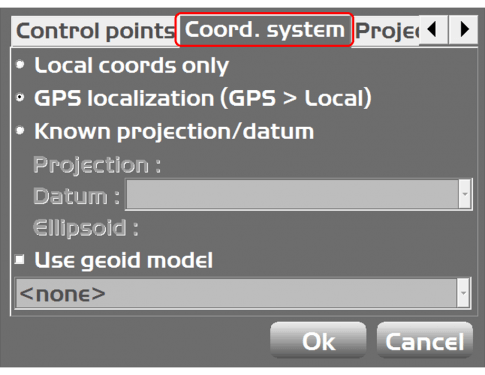
- Under the Coords tab the operator can select the type of coordinate system they will be working with.
- Local cords only is when running the 3D system from a total station (LPS) and a GPS localization is not required.
- GPS localization (GPS>Local) is used when running a 3D system with GPS.
- Known projection/datum is used if the project is running on a projection.
- Information for LPS and Projections will be covered in additional lessons.
Add Control Points
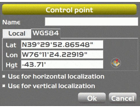
- The Add button would allow an operator to add additional Control points into the control file.
- This may be used if a project doesn’t have any established control and the operator can add a point and do a single point localization directly from the machine.
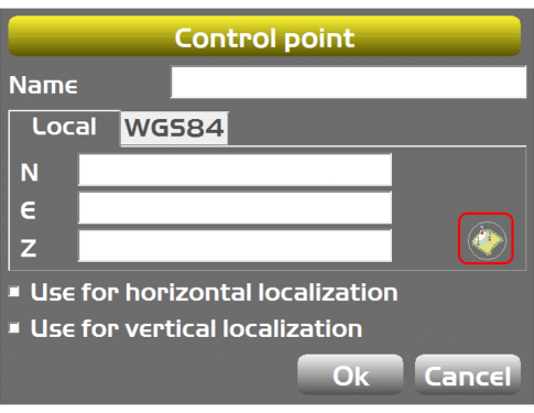
- After selecting the Add option form the Control points screen, the operator would enter the Local coordinates for the point being added.
- The icon (outlined in red )allows the operator to select a point form a point file within the project as a Control point.
- The Use for horizontal/vertical check boxes allow the operator to turn on or off the horizontal or vertical value of the control point.
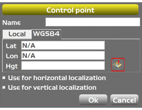
- The WGS84 tab is where the operator can localize the selected point.
- The button (outlined in red) will perform the localization by taking a 3 second sot on the point. The Lat/Lon/Hgt values will be filled in with GPS coordinates and associated to the local coordinates manually entered.
- After selecting the button (outlined in red in the previous slide) , the following screen allows the operator to select the type of antenna and the height of the antenna for the localization process.
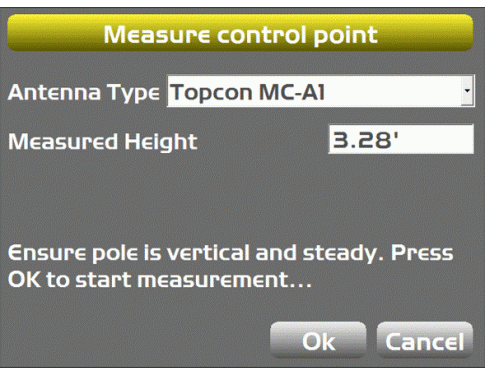
- After pressing the button (outlined in red) the system will take a 3 second shot and attach WGS84 coordinates to the control point
