Hardware Troubleshooting
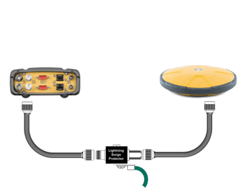
Reference Stations operate continuously. They are the 24/7 workhorse of the Survey and Construction community. While they are built to last, there are times where they need attention. Failures generally fit into one of two categories; Hardware or IT. This Quick Guide will focus on the hardware and what we can do to remedy common issues. Hardware can fail in several places, either individually or all together. The 3 main components of a typical Reference Station are:
- Receiver
- Antenna
- Cable

Receiver Failures
Receiver failures are rare but do happen, especially as we encounter older installations with the original equipment. What is more likely to present is a receiver that has locked up and not responsive. The first and most importand step is to see what the front panel LEDs are showing.
- Is the POWER button lit
-
Is the receiver tracking
- The STAT LED should be alternating between Green and Amber
-
Does it have a network link
- The LINK LED should be solid Green
IF the receiver appears to be "normal", a power cycle may be all that is needed. Periodically, the power cycle doesn't seem to fix the issue. At this point a hard reset is needed. On the NetG3(A), under the front panel there is a reset button. Use a paper clip to press the reset.
The NetG3A has been the victim of a specific lockup. This occurs in a managed network environment where the host's router/firewall is sniffing HTTP ports for potential threats/exploits. Repeated probing of the HTTP ports will cause the NetG3A to enter into exception mode. The classic symptom will be a STAT LED will be solid Red or will return to Red after a power cycle attempt. The ONLY fix is a paper clip reset. If this is found, advise the TopNET live admin and a specific OAF can be generated and loaded to disable the web interface.
Not Tracking?
If the reference Station isn't tracking satellites then a deeper troubleshooting process is needed. There could be as many as 3 possible sources of the failure.
-
Test the Receiver
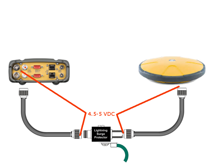
- Pull the coaxial connector from the rear panel. With a voltmeter set to DC voltage, place one probe on the center pin and the other on the outer rim of the connector. If the receiver outputs approximately 4.5 - 5 Volts DC, then the receiver is most likely OK. If not, the receiver is probably bad and needs to be replaced
-
Test the Cable
- Using a voltmeter, like the receiver test, check the voltage at each break in the cable. The Same 4.5 - 5 volts should be measured. If there is good voltage at the receiver but not at any of the connectors in the cable, then suspect a bad cable. Try replacing the connectors on the cable first. Connectors can leech moisture into the cable causing corrosion in the last 3-6 inches.
-
The Antenna
- If we have voltage all along the cable and still not tracking, then the only peice left is the antenna. Replace it.
