UAS Component Inspection (Fuselage)
- For details on the aircraft inspection checklist, please refer to section 4.2.3 of the MAVinci user’s manual.
- Remove the UAV fuselage from the transport case and remove the plastic sleeve. Confirm if there is any noticeable damage anywhere on the UAV fuselage foam which may affect flight operations. Repair with white or black duct tape if possible/as necessary.
- Inspect the UAV propellers for any cracks or damage. Replace as necessary.
- Confirm that the UAV propellers are properly secured to the UAV engine. There should be some resistance when extending/retracting the propellers.
- Confirm that the UAV engine spins freely when rotating in both directions and there isn’t any grinding due to dirt or debris.
- Inspect the electrical connectors for the horizontal and vertical stabilizers on the UAV fuselage. Confirm that there is no debris inside each of the connectors as well as no bent or broken pins on each of the connectors.
- Inspect the electrical connectors used for the left and right wings located on the top of the UAV fuselage. Confirm that there is no debris inside each of the connectors as well as no bent or broken pins on the connectors.
- Open the cockpit canopy and inspect the internal plastic skeleton. Confirm that there are no cracks or damage.
- Confirm the GNSS antenna on the top of the UAV fuselage is firmly attached.
- Confirm that the cooling vents on both sides of the UAV fuselage are clear of dirt and debris.
UAS Component Inspection (Stabilizers)
- Remove the vertical and horizontal stabilizers from the transport case.
- Confirm if there is any noticeable damage anywhere on the vertical and horizontal stabilizer foam which may affect flight operations.
- Inspect the glue used to secure the servos of the vertical and horizontal stabilizers. Confirm the glue is still secured to the stabilizers.
- Inspect the servo rods of the vertical and horizontal stabilizers. Confirm they are not loose or broken.
- Inspect the vertical and horizontal stabilizer electrical connectors. Confirm they are not cracked or broken.
- Inspect the cables for the electrical connectors on the stabilizers and confirm they are not frayed, cut, or torn.
- If there is any damage to the stabilizer’s foam, repair with white duct tape if possible. If not possible, replace the stabilizer as necessary.
- If there is any damage to the servo rods, electrical connectors, cables, etc., replace the stabilizer as necessary.
- Once finished with the inspection, return the vertical and horizontal stabilizers to the transport case.
UAS Component Inspection (Wings)
- Remove the left and right wings from the transport case.
- Confirm if there is any noticeable damage anywhere on the left and right wing foam which may affect flight operations.
- Inspect the glue which is used to secure the servos of the left and right wings. Confirm the glue is still secured to the wings.
- Inspect the servo rods of the left and right wings. Confirm they are not loose or broken.
- Inspect the left and right wing electrical connectors. Confirm they are not cracked or broken.
- Inspect the cables for the electrical connectors for both wings and confirm they are not frayed, cut, or torn.
- If there is any damage to the left or right wing foam, repair with white duct tape if possible. If not possible, replace the wing as necessary.
- If there is any damage to the servo rods, electrical connectors, cables, etc., replace the wing as necessary.
- Once finished with the inspection, return the wings to the transport case.
UAS Component Inspection (Connector)
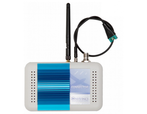
- Inspect the WLAN connector antenna and confirm that it isn’t cracked or broken.
-
Inspect the WLAN connector battery cable:
- Confirm the electrical connector for the LiPo battery doesn’t have any broken or bent pins.
- Confirm the electrical connector for the WLAN connector isn’t cracked or broken.
- Confirm the cable isn’t frayed, cut, or torn.
- Inspect the WLAN connector GNSS Antenna port:
- Confirm the antenna port isn’t bent or broken.
- Confirm that the antenna port is not loose and is secured on the WLAN connector.
-
Inspect the WLAN connector wireless antenna port:
- Confirm that the antenna port isn’t bent or broken.
-
Inspect the WLAN connector power port:
- Confirm that the power port isn’t bent or broken.
-
Confirm the following on the WLAN connector:
- The wireless antenna can be securely attached.
- The WLAN connector power cable can be securely attached.
- The GNSS Antenna port can be securely attached to a GNSS antenna cable.

UAS Component Inspection (RC)
-
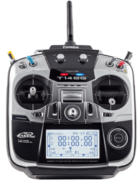
Confirm the following on the RC antenna:
- The antenna can be adjusted accordingly and is also firmly attached.
- The antenna is not bent, cracked, or broken.
-
Confirm the following on the RC switches:
- Automatic/Assisted mode switch can toggled back and forth accordingly.
- Manual/Autopilot switch can be toggled back and forth accordingly.
- Landing switch can be depressed and returns to default position once released.
-
Confirm the following on the RC control sticks:
- Confirm that the left stick moves freely in all directions and returns to the center position once released.
- Confirm that the right stick moves left and right freely and returns to the center position once released.
- Confirm that there is slight resistance when moving the right stick up and down (i.e. the throttle).

UAS Component Inspection (LiPo)
-
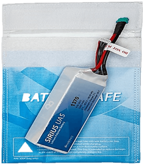
Confirm for all LiPo batteries to be used that the battery itself has no physical damage and is not bulging or deformed in any way.
- If there is any damage or deformity, do not ever use that battery with the UAS.
-
Confirm the following on the battery connection cable and the balancing cable:
- The battery cable is not frayed, cut, or torn
- The electrical connector is not cracked or broken.
