3D-MC Max Machine Builder
Reference Material
3D-MC Max Quick Guide 1010717-01
3D-MC Max Dozer Install Manual 1009522-01
Verify FW and SW - Check for Max .mx3 Options
If loading FW and SW. Firmware needs to be loaded before GNSS Oaf’s (.tpo)
Confirm 3DMCMax Auth Code (.oaf) is Enabled/Yes on GX-55Create Configuration Name/Type: 3D Max
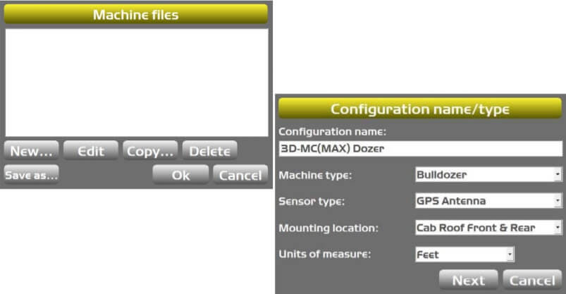
Mounting location: Cab Roof Front & Rear
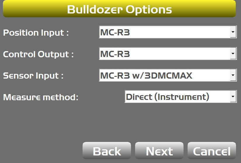
Dozer Options
Sensor Input: 3DMCMAX
Measure method: Direct (Instrument)
Measure machine
Create New 3D-MC Max Machine Builder
Create Machine Builder
In the 3D-MC Max main screen
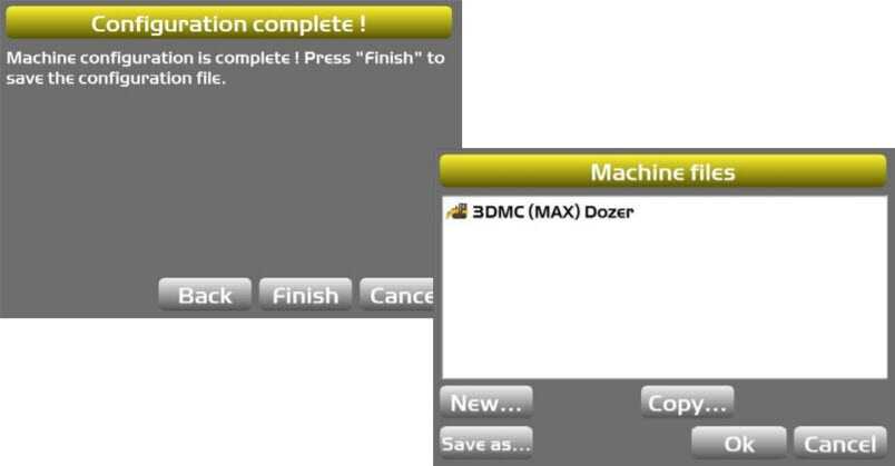
Tap Power Button (GX-55)>Control>Machine Setup. The Machine files appear.
Tap New. The Configuration name/type appears
Enter machine name: Max Dozer
Mounting Location: Select Roof Front/ Rear or Single
Bulldozer Options
Measure Method
Tape Measure: Uses slant measurements to determine antenna height/position
Direct (Instrument): Uses straight-line measurements from a laser/total station to establish antenna height/position.
Direct (Instrument) recommended: Tape measure has room for error with track sag, angle of tape to track, surface side slope
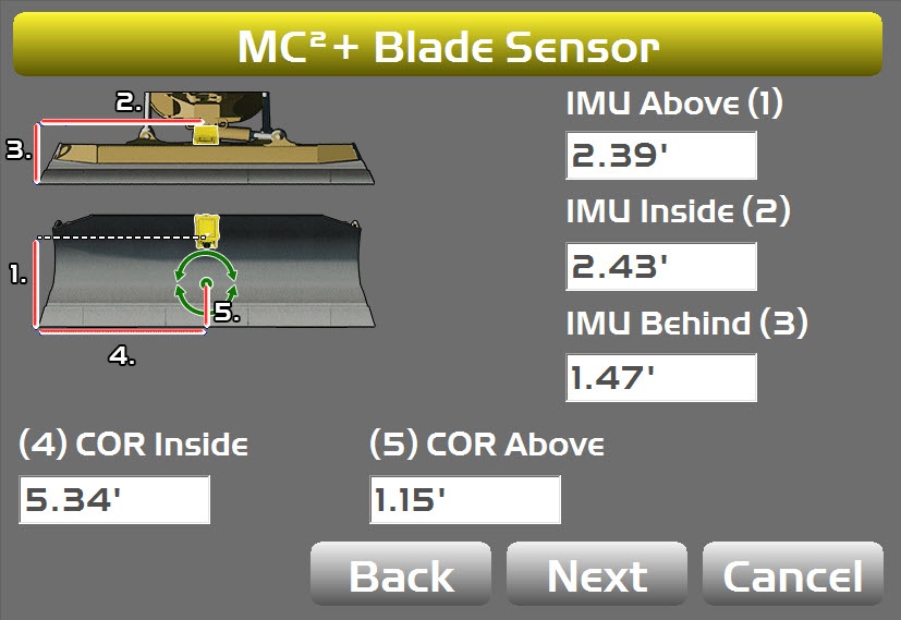
Direct (Instrument) Measurements Blade Sensor
MC2+Blade Sensor
COR same as conventional 3DMC2
All measurements are from the right side of the blade sitting in the cab.
Measure to Reference Point on IMU
IMU Above: From cutting edge to IMU RP
IMU Inside: From right cutting edge/end bit of blade to IMU RP.
IMU Behind: From cutting edge to IMU RP
COR Inside: Center of Blade Rotation to right side of cutting edge
COR Above: From cutting edge to Center of Blade Rotation
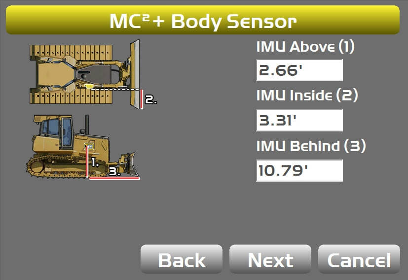
Direct (Instrument) Measurements Body Sensor
MC2+ Body Sensor
IMU Above: From cutting edge to Reference Point on sensor
IMU Inside: From right corner of blade to Reference Point on sensor
IMU Behind: From cutting edge to Reference Point on sensor
Body IMU Sensor mounted at Center of Dozer Body (not shown in this picture)
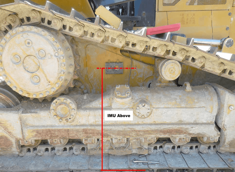
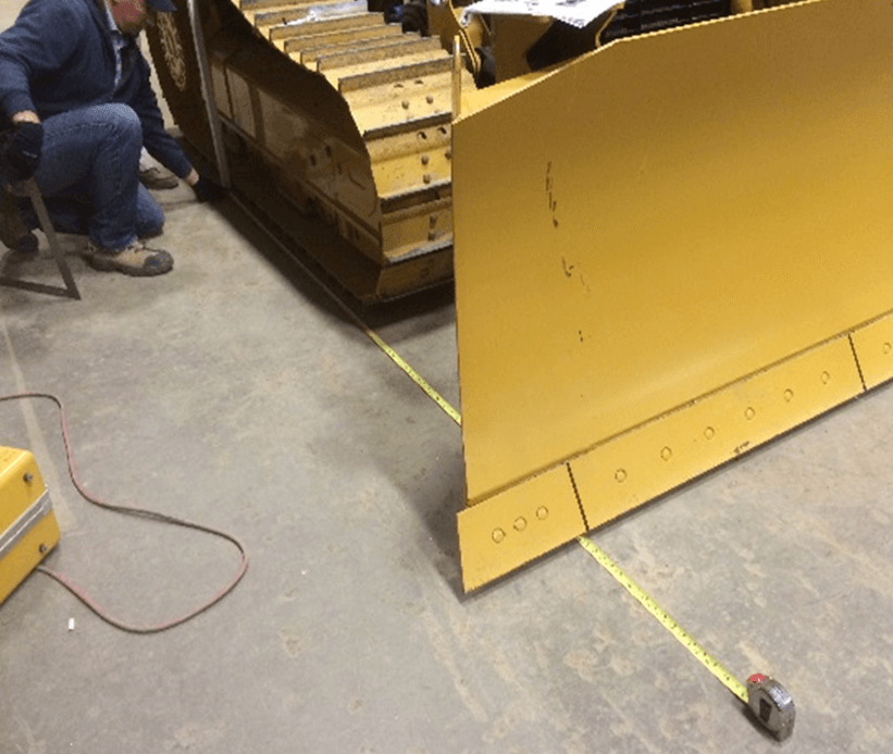
Performing this calibration requires flat surface between Blade edge and IMU for accurate measurement.
IMU Above Measurement
Use a level to transfer the Reference Point on the sensor to outside the tracks
Measure down with a tape measure to establish Body IMU Above measurement
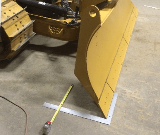
IMU Inside Measurement
Use a framing square to establish right angle at corner of blade
Lay a grade rod down on the square and parallel to the track edge
Measure over from the reference point of the body sensor to the grade rod
IMU Behind Measurement
Use a level to transfer the Reference Point on the sensor to outside the tracks
Drop a plumb bob to the ground and mark it with a marker or paint
With the blade slightly raised, slide a tape measure under the blade back to the plumb bob mark
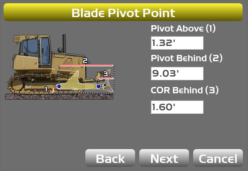
Blade Pivot Point
Pivot Above: From body pin on A-frame to center of tracks
Pivot Behind: From cutting edge to body pin on A-frame
COR Behind: From cutting edge to center of rotation
Pivot Above on most machine are difficult to get to
Pivot Above is important, this calculates antenna height
Blade Pivot Point is reference for Max system
Pivot Above
Use a tape measure to measure up from ground to the Reference Point
Pivot Behind
Drop a plumb bob to the ground and mark it with a marker or paint
With the blade slightly raised, slide a tape measure under the blade back to the plumb bob mark
COR Behind
Raise the blade slightly off the ground
Drop a plumb bob down from Center of Rotation
Measure from plumb bob to cutting edge to establish COR Behind
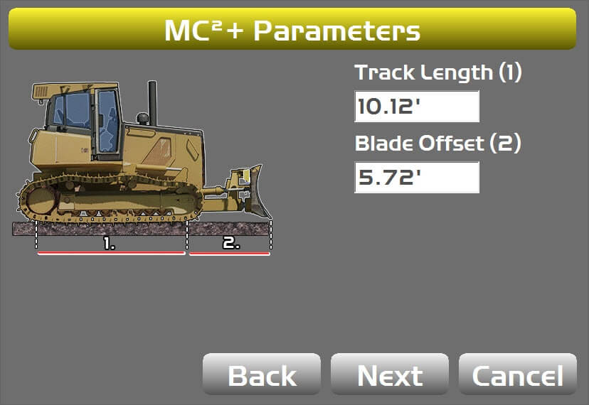
Track Length Blade Offset to Tracks
Track Length: Center of front roller to center of rear sprocket
Blade Offset: Cutting edge to center of front sprocket
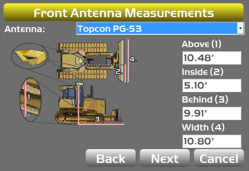
Front Antenna Measurements
Above: From slot on bracket to cutting edge
Inside: From right corner of blade to right side of bracket (not antenna center
Behind: From cutting edge to back of slot on bracket
Width: Width of cutting edge
All measurements are to the notch on the antenna bracket
Important to be on a flat surface making measurement
Front Antenna Above measurement used with Blade Pivot Above measurement for antenna height
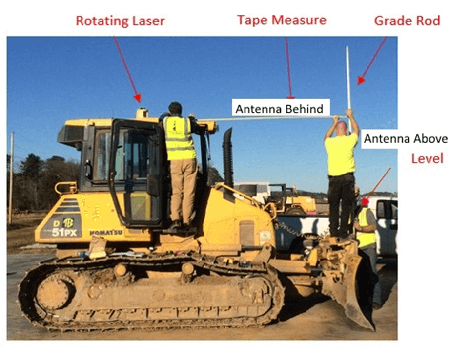
Establishing antenna above and behind measurements with Direct method
Laser
4’ Level
Tape Measure
Telescoping Rod
Many different methods to Direct (instrument) measure antennas for 3D-MC Max
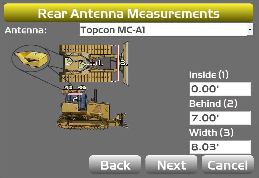
Rear Antenna Measurements
Inside: From center of front antenna to center of rear antenna offset
Behind: From of front antenna to center of rear antenna
Width: Width of machine measuring tracks
3D-MC Max Machine Build Complete
Direct (Instrument) Measurement Complete
For best result, measure and calibrate on a flat planar surface
Important to have Front Antenna Above and Blade Pivot Above measurement very accurate
PS recommends Direct (Instrument) Measurement
System will not transfer measurements from Tape to Direct measurements
When making new .mx3 the slope calibration do not carryover.