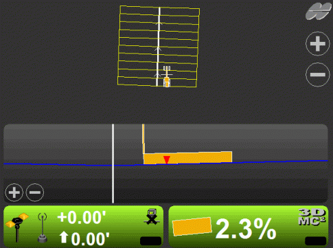
Crown Road Surface
Creating a Crown road surface is similar to creating a sloping surface with the addition of defining the length and width of the crown road surface.
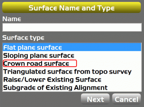
Creating a Crown Road Surface is a simple process. The operator will need to enter four elements for the crown road surface.
- Starting Point: Will set the elevations of the surface as it did when creating a Flat/Sloping Plane Surface. The elevation is typically set after the surface has been defined.
- Main-fall: Will define the direction of orientation of the Centerline and set the slope Grade of the centerline. This step is typically done first.
- Cross-fall from crown: Will define the cross slope left and right of the centerline.
- Width of road: Defines the overall width of the road.
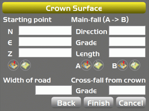
Crown Surface (Setting Direction/Grade)
Setting the Centerline can be achieved a few different ways.
- Direction/Grade: If a GPS heading of the centerline is known the operator can enter the heading value in the Direction Box and set the grade at the defined heading.
- Length: Will define the total length of the centerline. The begining of the centerline will start at the A point and end at the B point. To continue the centerline further beyond point, enter the desired length from point A. This will continue the centerline beyond the B point.
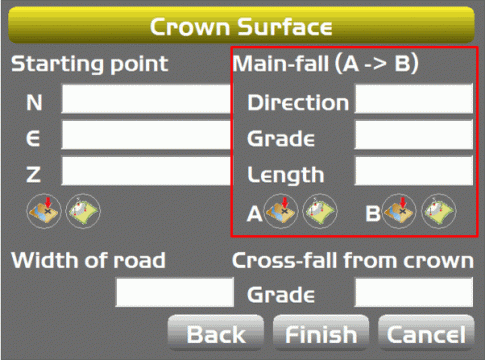
Setting the Main Slope of the Centerline can be achieved a few different ways.
- If the operator has a set of points for the centerline in the points file they can select the points using the select point button.
- When using the select point option the Direction/Grade will be set from the elevations of the points.
- The Direction and Grade can be edited by simply selecting either the Direction or Grade and changing the values.
- A positive or negative slope is determined by defining the direction of the points selected. From A to B a slope heading uphill is positive.
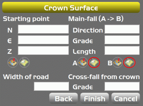
Crown Surface (Setting Direction/Grade from Topo Shot)
Setting the Main Slope of the centerline can be achieved a few different ways.
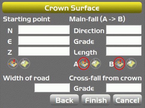
- The operator can use the A/B buttons to take survey shots using the machine to set the Direction and Grade of the centerline.
- Survey Shots will be taken from the last point of steering the machine used.
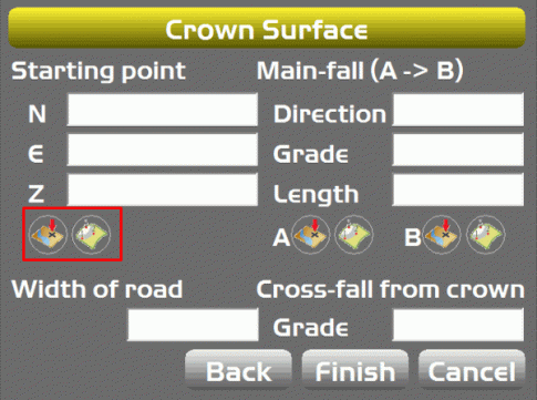
Crown Surface (Setting Elevations)
The operator can set the proper elevation by either
- Selecting a point from the points file which has the correct elevation.
- Taking a topo shot on a known elevation.
Once the Crown Surface has been defined any of the values can be changed, if required.
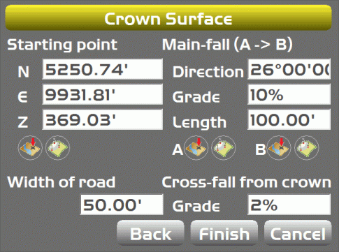
The surface that was created was a ditch 100' long and 50' wide with 2% slope flowing along the centerline.
